What is SureFlow®?
SureFlow® is an innovative approach to flexible cooling and heating hydronic system design.
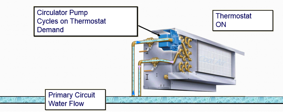
The key component of a SureFlow® system is a custom designed fancoil (see image) with an integrated low watt circulator(s). The circulator delivers the design water flow through the coil and back to a primary loop. This allows the individual fan coils to be hydraulically isolated from one another and be decoupled from the distribution primary loop. A benefit of this arrangement is the ability to satisfy the comfort requirements of a cooling-only system with one pipe instead of two and for a cooling and heating system with two pipes instead of four.


Since the primary pump is no longer responsible for overcoming the valve and coil losses, and is only responsible for moving the water in the primary loop, the horsepower demand is reduced significantly resulting in energy savings.
How Does SureFlow® Work
Multiple SureFlow® units are placed in series on a primary loop. The primary loop has a constant water flow that is engineered to satisfy the total BTU demands of the loop at peak load conditions.
Image below: 48,000 BTU/H; 42°F EWT; 10°F ΔT; 9.6 GPM Primary

In the example shown above, four coils are connected to a loop with a peak load of 48,000 BTU/H. The designer plans for a 10 degree water temperature rise from the loop and configures the primary for 9.6 GPM of water flow with an initial temperature of 42 degrees. The primary loop is set up for constant water flow while the SureFlow® units cycle on local thermostat demand. As each unit cycles on, the local circulator “borrows” water for use in the coil and then returns the used water to the loop. The blended water then becomes the inlet water for the next operating unit. Units are selected to operate at the available water temperature.
Parallel Flow vs. SureFlow®
In parallel flow hydronic systems (see image below), a central pump delivers constant water temperature throughout the building to each fan coil unit. The central pump must overcome system head losses (piping, balancing valves or circuit setters, fittings, accessories, zone control valves) and still produce sufficient pressure to push water through the coil. Unfortunately building diversity causes problems balancing flow at actual operating conditions. Parallel flow systems are “design specific,” making changes in zoning difficult to implement.
Image below: Basic Two-pipe Direct-return Piping Diagram

SureFlow® System
In SureFlow® systems, flow controls and zone control valves are removed from the fan coil unit. The central pump moves water past the fan coil units in a primary circuit called a “SureFlow® Loop.” The integral circulator delivers the rated flow to each unit and cycles on demand of the local thermostat.
Image below: Single-pipe, Primary/Secondary SureFlow® System


Design Tools
A SureFlow® Rating Program and Loop Simulator are available for use by the design engineer.
The SureFlow® Rating Program includes the following:
- Individual selection at specific criteria
- Intelligent format allows standard models and coils to be selected.
- Provides performance rating data
- Includes schedule builder
- Provides submittal drawings
- Provides sample specifications
The SureFlow® Loop Simulator includes the following:
- Models individual unit performance at selected design conditions
- Allows units to be modeled at multiple fan speeds or cycled off
- “AUTO SELECT” function automatically selects unit sizes and coil rows
- Displays total capacity, sensible capacity, and latent capacity for each unit
- Charts entering, leaving, and mixed water temperatures
- Loop performance is displayed graphically
- Allows fast, interactive system design
SureFlow® Models
For more than 60 years International Environmental Corporation (IEC) has been developing the largest depth and breadth of fancoils in the industry. IEC’s SureFlow fancoils are available in horizontal and vertical units, as well as modular hi-rise. Click here for a detailed list. Contact Michigan Air Products to discuss you next fancoil application.
